47 Synthesizable Digital Temperature Sensor
47 : Synthesizable Digital Temperature Sensor
- Author: Harald Pretl
- Description: Measure the on-chip temperature and display on the LED display.
- GitHub repository
- Clock: 10000 Hz
How it works
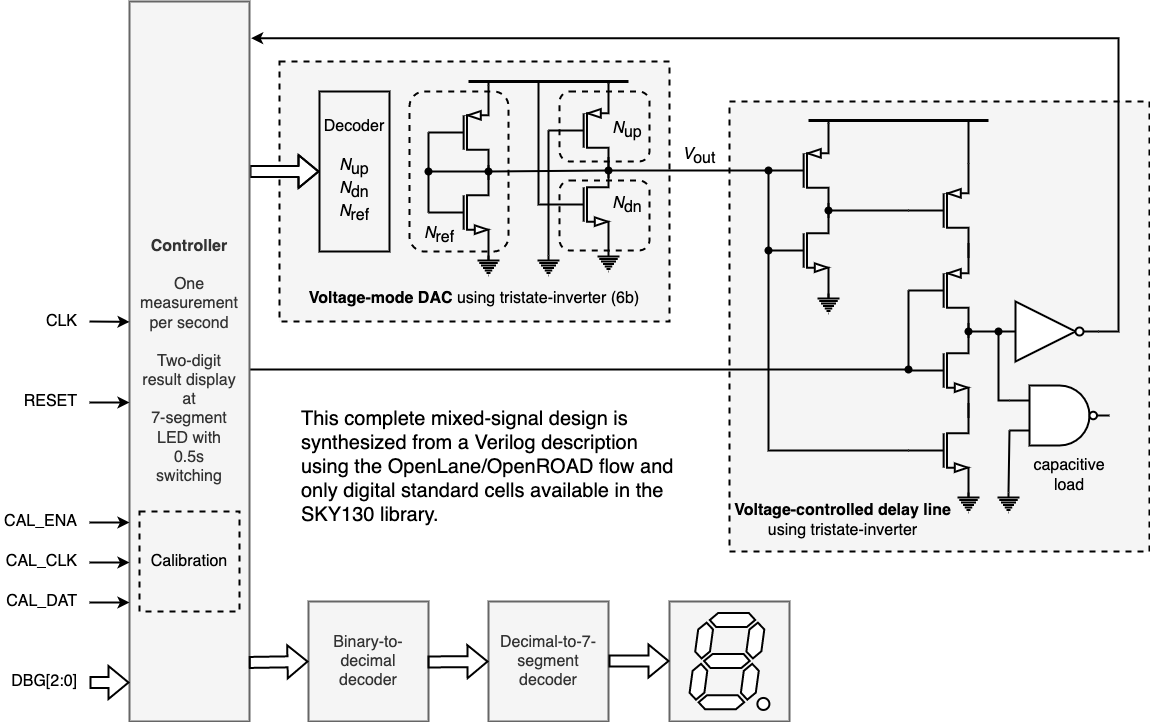
By creatively twisting the use of a tristate-inverter (EINVP) a voltage DAC is built. This voltage-mode DAC is used in another twisted arrangement of an EINVP to bias an NMOS into subthreshold operation to discharge a pre-charged capacitor (the input capacitor of an inverter). Since the subthreshold current of a MOSFET is a strong function of temperature, the resulting delay time is also a strong function of temperature, thus a digital temperature sensor is built.
The temperature-dependent digital signal is output at the LED display, showing tens (dot off) and ones (dot on).
A calibration engine via a LUT is included, to allow to linearize and calibrate the shown temperature code.
io_in[0] is used as a CLK signal, and io_in[1] is used a RESET.
io_in[4:2] is used to load and enable the calibration engine.
io_in[7:5] is used to enable various debug modes, presenting internal state signals to the io_out.
How to test
After reset, one temperature measurement is taken per second and displayed using the LEDs. A code ranging 0...63 is displayed with tens first (dot off) and ones later (dot on).
During normal operation io_in[7:5] have to be set to 000. The different debug modes are documented in the Verilog code.
For calibration, the internal LUT can be serially loaded by using CAL_CLK (io_in[2]) and CAL_DAT (io_in[3]). Once fully loaded the calibration engine is enabled by setting CAL_ENA (io_in[4]) to 1 (setting it to 0 displays the raw sensor code).

IO
| # | Input | Output |
|---|---|---|
| 0 | clock | segment a (or debug information) |
| 1 | reset | segment b (or debug information) |
| 2 | cal_clk | segment c (or debug information) |
| 3 | cal_dat | segment d (or debug information) |
| 4 | cal_ena | segment e (or debug information) |
| 5 | debug_mode[0] | segment f (or debug information) |
| 6 | debug_mode[1] | segment g (or debug information) |
| 7 | debug_mode[2] | indicate ones or tens (or debug information) |