Tiny Tapeout > Tiny Tapeout Chips > Tiny Tapeout 2 > 112 Low-speed UART transmitter with limited character set loading
112 Low-speed UART transmitter with limited character set loading
112 : Low-speed UART transmitter with limited character set loading
- Author: maehw
- Description: Low baudrate UART transmitter (8N1) with limited character set (0x40..0x5F; includes all capital letters in the ASCII table) loading.
- GitHub repository
- Clock: 9600 Hz
How it works
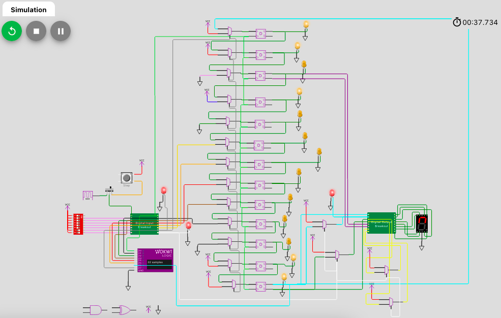
The heart of the design is a 13 bit shift register (built from D flip-flops). When a word has been transmitted, it will be transmitted again and again until a new word is loaded into the shift register or the output is disabled (the word will keep on cycling internally).
How to test
Load a character into the design and attach a UART receiver (or oscilloscope or logic analyzer) on the output side.
External hardware
UART receiver or oscilloscope or logic analyzer (optional)
IO
| # | Input | Output |
|---|---|---|
| 0 | 300 Hz input clock signal (or different value supported by the whole | UART (serial output pin, direct throughput) |
| 1 | bit b0 (the least significant bit) of the loaded and transmitted character | UART (serial output pin, gated by enable signal) |
| 2 | bit b1 of the loaded and transmitted character | UART (serial output pin, reverse polarity, direct throughput) |
| 3 | bit b2 of the loaded and transmitted character | UART (serial output pin, reverse polarity, gated by enable signal) |
| 4 | bit b3 of the loaded and transmitted character | UART (MSBit, direct throughput); typically set to 1 or can be used to sniffing the word cycling through the shift register) |
| 5 | bit b4 of the loaded and transmitted character | UART (MSBit, reverse polarity, direct throughput); same usage as above |
| 6 | load word into shift register from parallel input (IN1..IN5) (1) or cycle the existing word with start/stop bits around it (0) | UART (MSBit, gated by enable signal); typically set to 1 or can be used to sniffing the word cycling through the shift register) |
| 7 | UART (MSBit, reverse polarity, gated by enable signal); same usage as above |